
11 kVHighest motor voltage in the cases below
Asset monitoring / Electric motors & VFDs
The motor is the sensor.
Start with its own health.
Rotor bars, stator windings, insulation, supply quality and VFD-induced bearing currents all change how a motor draws current. Artesis reads them at the MCC — for LV and MV motors, on DOL, soft-starter or VFD.
4 field casesPharma, power, glass and process
0 sensors on the motorCurrent and voltage measured in the MCC
01 / The challenge
Every asset has a motor.
Few are watched.
Motors drive pumps, fans, compressors and conveyors in every plant. Electrical faults — insulation breakdown, broken rotor bars, loose windings — can take a motor from normal to burnt in days.
VFDs add another risk: common-mode voltage can drive currents through the bearings and etch them. ESA reads both the motor’s electrical health and its mechanical condition from the same three phases.
Connect at the motor control cabinet
e-MCM uses the existing current and voltage signals, via CT/PT secondaries on MV motors.
Learn the motor’s signature
A model of each motor–load set is built under real operating conditions, including VFD speeds.
Separate motor from load
Findings distinguish stator, rotor, supply and bearing issues from driven-equipment problems.
02 / Featured case · Pharmaceutical
Bearings etched by the drive.
Shaft grounding confirmed as the fix.
DOCUMENTED FIELD CASECHILLER MOTOR / VOLTAGE AND CURRENT WAVEFORMS
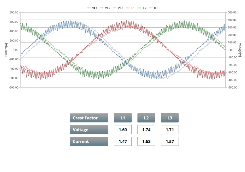
Distorted waveforms and elevated crest factors from the VFD.
CHILLER MOTOR / BEFORE AND AFTER SHAFT GROUNDING
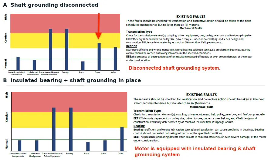
A: grounding disconnected, stator indicator in caution. B: grounding in place, back to normal. Select to open full size.
A → B
Same motor, same day, one change
With the shaft grounding reconnected, the stator-related indicator dropped from caution back to normal.
Premature bearing failures, explained.
480 VNominal voltage
VFDDrive
ChillerDriven equipment
The problemA pharmaceutical site kept losing drive-end bearings on a VFD-driven chiller motor. The DE bearing had no insulation.
The findingAMTPro showed distorted waveforms and high crest factors — the conditions that drive bearing currents and electrical arcing. Maintenance found the fluting pattern on the failed bearing.
The confirmationTests on the same day with the shaft grounding disconnected and connected showed the stator-related indicator return to normal once the insulated bearing and grounding were in place.
- 1Repeated DE bearing failures
- 2Distorted waveforms, bearing currents
- 3Insulated bearing + shaft grounding
Source: Artesis Case Study 2024, slides 9–14, and AMTPro reports (June 2023). Customer name withheld.
03 / More field cases
Rotor bars
and stator windings.
3 INDUSTRIES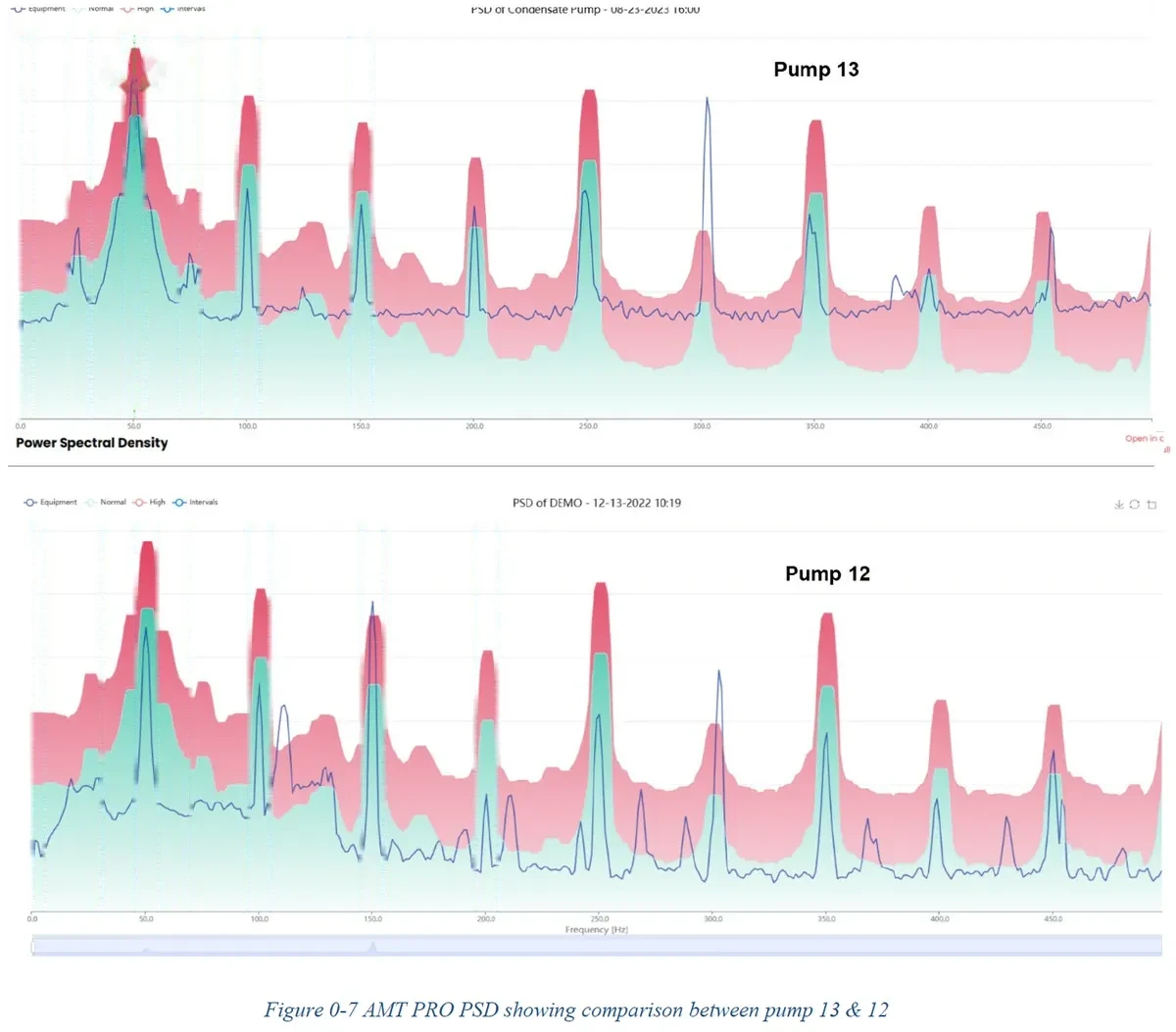
Cracked rotor bars on an 11 kV motor
A rotor-related pattern appeared on one of two identical condensate pump motors. An offline rotor test, repeated three times, confirmed cracked or defective rotor bars.
- Rating
- 11 kV · 32 A · 510 kW
- More
- Pump page →
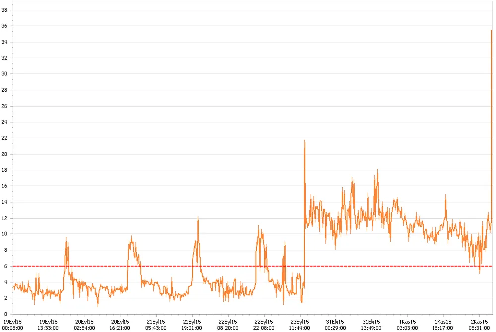
Loose windings rubbing the rotor
After five weeks out of service, a turbo compressor motor restarted and its internal electrical fault trend jumped. Three days later it was stopped: the stator windings had loosened and were rubbing the rotor.
- Duty
- Turbo compressor
- Outcome
- Stopped before a major failure
Fluting found where vibration missed it
An AMTPro test on a VFD-driven mixer indicated an outer-race bearing fault. Inspection found electrical fluting on the race — damage a vibration route had not caught.
Cases are individual outcomes from Artesis field deployments between 2005 and 2023. All visuals are from Artesis software. Customer names are withheld.
04 / What we detect
Fault modes, signals
and evidence strength.
Evidence strength reflects how reliably a condition produces an observable electrical pattern in typical motor installations — not a guarantee of detection.
| Condition | What changes in the signal | Evidence | Field case |
|---|---|---|---|
| Motor · electrical | |||
| Broken or cracked rotor bars | Rotor-related pattern in the current spectrum | Strong | 11 kV pump motor |
| Stator windings, turn-to-turn | Internal electrical fault indicator and phase balance | Strong | Turbo compressor |
| Insulation breakdown | Internal electrical fault trend, phase imbalance | Strong | — |
| Supply quality and connections | Voltage imbalance, THD, harmonics, per-phase RMS | Strong | — |
| Motor · VFD effects | |||
| Bearing currents and fluting | Waveform distortion, crest factor and bearing-related indicators | Good | Chiller motor → |
| Shaft grounding effectiveness | Indicator change with grounding in/out | Good | Chiller motor |
| VFD switching (IGBT) problems | Drive switching-related pattern in the high-resolution spectrum | Good | — |
| Motor · mechanical and load | |||
| Motor bearings | Bearing-related pattern in the current spectrum | Good | VFD mixer |
| Eccentricity and soft foot | Mechanical pattern in the current spectrum | Good | — |
| Oversized or underloaded motors | Load below ~60% of rating; energy effect | Strong | See fan pages |
05 / Outside the envelope
Where electrical signatures are weaker.
We state the limits up front, so monitoring is set up where it adds most and paired with the right complementary checks.
Motors off most of the time
Standby motors need running time for data; use AMTPro when they run.
Very low VFD speed
Below about 20 Hz, diagnostic confidence is reduced.
Insulation to ground at rest
Offline insulation tests (IR, PI, surge) remain the tools for de-energised checks.
DC and special motors
Methods target AC induction motors; others need review case by case.
Observed patterns are interpreted by qualified personnel; they guide investigation rather than replace it. AMTPro spot tests need near-constant speed (±1% frequency) during capture.
06 / How you deploy it
Continuous where it matters.
Portable everywhere else.
Online · permanently installed
e-MCM
- Critical LV and MV motors
- 24/7 learning, trending and alarms
- Supports VFD applications
- Results in OmniSight across sites
Portable · route-based
AMTPro
- Fleet screening across hundreds of motors
- Spot tests from the MCC in minutes
- Automatic condition report per test
- Energy impact estimate in every report
Artesis Insight explains the finding.
Artesis Insight turns spectra and trends into plain-language explanations and next steps. Your team does not need to be an ESA specialist to act on a result.
Illustrative maintenance guidance
Check for VFD bearing currents.
Distorted waveforms with high crest factor and bearing-related indicators suggest bearing currents. Check shaft grounding, insulated bearings and drive output filtering.
After action
Re-test with mitigation in place and confirm the indicators return to normal.
Example wording only; not a live alarm or a reproduced AI report.
07 / Applications
Any AC induction motor, any driven load.
LV induction motors from 1 kWMV motors via CT/PT secondariesVFD-driven motorsSoft-starter and DOL motorsStandby and spare motorsMotors in hazardous areas
Which motors can be monitored?
AC induction motors, low and medium voltage, on DOL, star-delta, soft-starter or VFD. MV motors are measured via existing CT and PT secondaries.
Can you detect VFD-induced bearing damage?
Yes. Distorted waveforms, high crest factors and bearing components point to bearing currents, as the featured chiller case shows.
Does it replace offline motor testing?
No. It complements it: ESA watches the running motor continuously; offline tests check insulation and windings when the motor is stopped.
Can hazardous-area motors be monitored?
Yes. The measurement is taken in the MCC, outside the hazardous area.
What information is needed to start?
Motor nameplate data, starter or drive type, driven equipment and the measurement points in the cabinet.
Related assets
Other equipment we monitor.
Bring your motors into view.
Tell us about your motor fleet. We’ll help you split it between online monitoring and portable routes.








 White Papers
 Case Study
 Documents
 Webinars
 Events
 ROI Calculator
 FAQ
FAQ