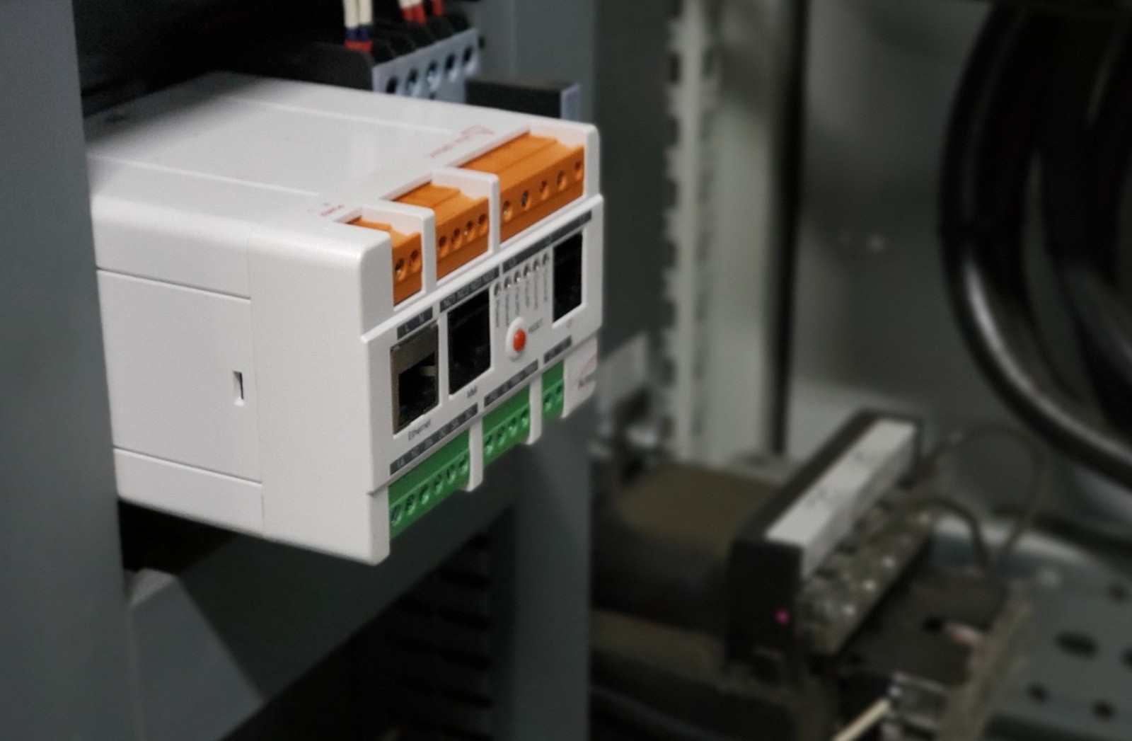
Install at the control cabinet.
Three-phase voltage and current from the generator's CTs, and its PTs above 690 V. Nothing is mounted on the generator, the engine or the turbine.
HOW IT WORKS
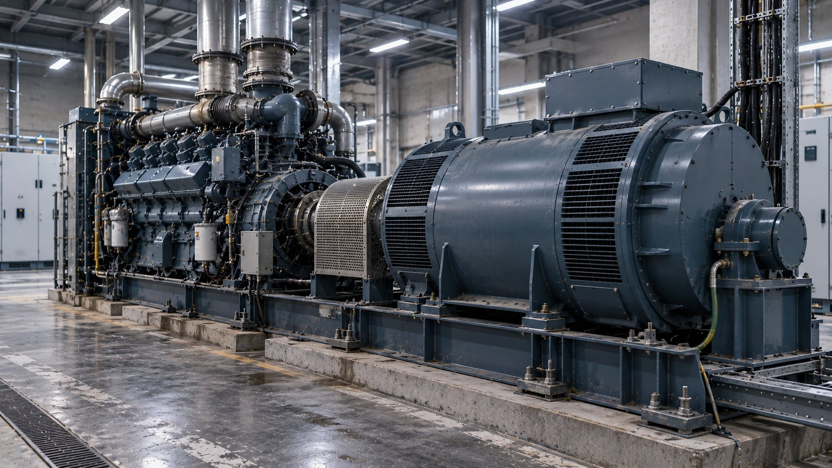
Faults in the generator, and mechanical conditions in its drivetrain, change the current and voltage at its terminals. e-PCM measures those signals at the control cabinet and compares them with the model it has learned for that generator.
Three-phase voltage and current from the generator's CTs, and its PTs above 690 V. Nothing is mounted on the generator, the engine or the turbine.
e-PCM builds a model of the machine from its own electrical behaviour across its operating conditions. Comparing similar units across a fleet adds context.
Persistent deviations are flagged by fault category, with what to inspect. Results show on the unit and go to plant systems. In OmniSight, Artesis Insight AI writes them up.
WHICH GENERATORS
Synchronous, induction and DFIG generators carry different signatures at their terminals. This is where e-PCM gives the most, and where it does not apply.
Salient-pole generators on a direct grid connection. Eccentricity, stator and excitation behaviour. Findings are checked against operating data, because hydraulic effects can resemble some rotor patterns.
Continuous and standby duty. Generator condition, plus prime-mover effects that show up in the generator's current, from one measurement. These machines often have little other monitoring.
Generator stator condition at the grid terminals. With an encoder speed reference, the gearbox and bearings are monitored too.
Generator condition and mechanical faults such as unbalance and misalignment. Turbine torque is smooth, so prime-mover faults are harder to place.
WIND TURBINES · DFIG
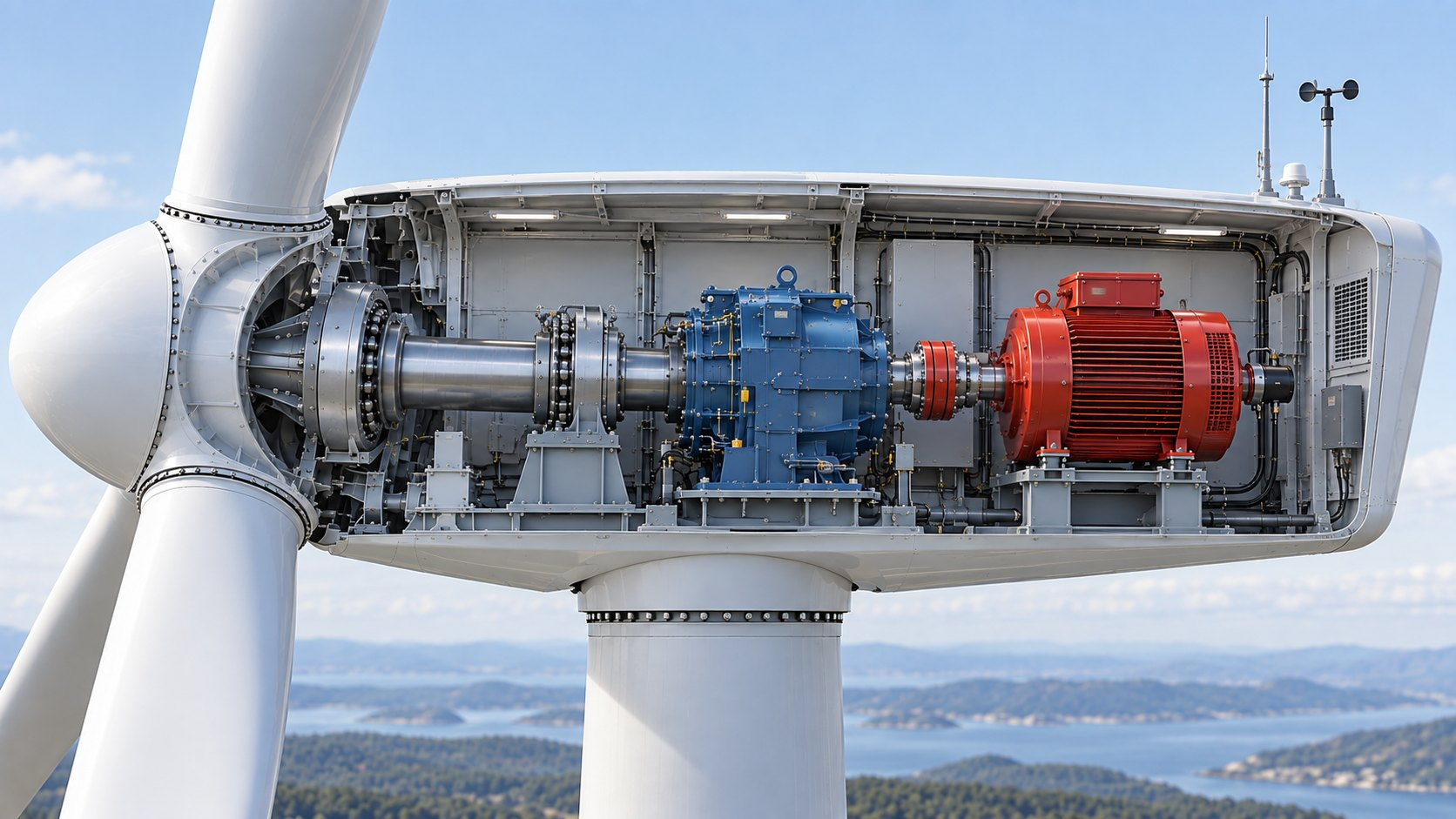
On DFIG wind turbines, e-PCM measures at the turbine's control cabinet, with no sensors added to the generator or gearbox. The turbine's encoder gives the speed reference for gearbox and bearing analysis. Select a component to see what e-PCM reports.
COVERED
Stator condition with the affected phase identified, rotor indications, and the generator's output and power quality at the terminals.
INSPECTStator winding and connections on the flagged phase.
COVERED
Gear mesh patterns in the generator current, placed against shaft speed from the encoder.
INSPECTGear mesh and gearbox bearings.
COVERED
Developing defects in the main, gearbox and generator bearings, placed against shaft speed. Where bearing geometry is known, it points to the bearing.
INSPECTThe flagged bearing, lubrication and mounting.
COVERED
Unbalance, misalignment and coupling condition in the drivetrain.
INSPECTShaft alignment, the coupling and mounting bolts.
INPUT, NOT MONITORED
The turbine's own encoder gives e-PCM the shaft speed. That speed is what lets gearbox and bearing patterns be placed.
SETUPEncoder signal wired to the e-PCM unit at the control cabinet.
NOT COVERED
Blade, pitch and yaw conditions are not covered by e-PCM.
INSTEADUse the turbine's own blade, pitch and yaw monitoring.
WHAT IT FINDS
Findings are reported by category. The recommended check confirms the cause on the machine.
MECHANICAL
Unbalance, misalignment, loose foundation and components, coupling. Inspection of balance, alignment, bolts and soft foot confirms the cause.
BEARINGS
Developing bearing defects, placed against shaft speed and, where known, the bearing geometry. On wind turbines, an encoder speed reference extends this to the gearbox.
STATOR
Current asymmetry judged against voltage asymmetry, and stator-related patterns in the spectrum, with the affected phase identified. Inspection confirms the specific cause.
ROTOR
Rotor category indication consistent with eccentricity, corroborated with operating data, especially on hydro units. Rotor bar patterns on induction and DFIG generators.
EXCITATION
Loss of excitation, abnormal power factor or reactive power at constant load, and voltage and reactive power oscillation.
POWER
Voltage and current imbalance, harmonic distortion, active and reactive power, power factor and frequency.
IN THE FIELD
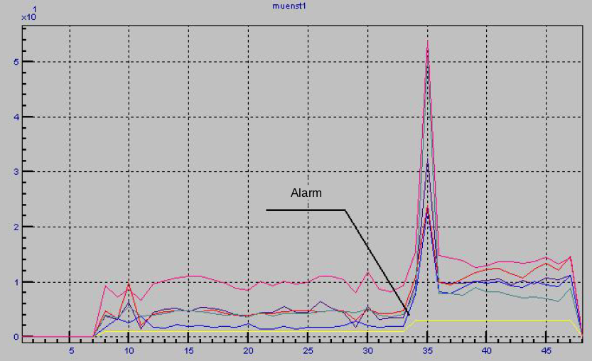
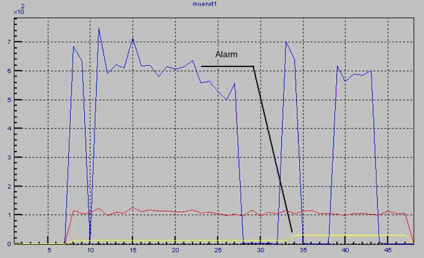
A 350 kW, 380 V, 1500 rpm diesel generator on a farm in Germany was fitted with Artesis monitoring alongside its existing monitoring system. Shortly after the learning period, its mechanical and electrical parameters began to rise.
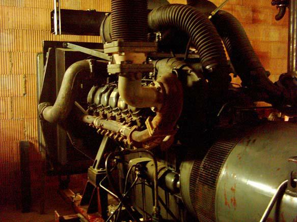
ALARM → WHAT HAPPENED
The mechanical parameters raised an alarm, then escalated to the examine level. The report pointed to the unbalance, eccentricity and coupling family.
The electrical parameters changed at the same time, corroborating a developing fault.
The generator's existing monitoring system gave no warning, so the generator stayed in service.
The generator failed. The examination found unbalance, which had progressed to contact between rotor and stator.
Shown as a record of what the electrical signature carried. The alarm was not acted on.
MORE FROM THE FIELD
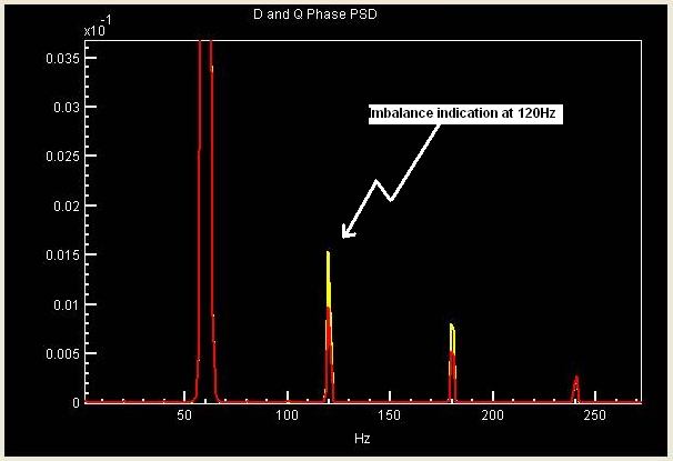
MECHANICAL · TURBINE GENERATOR
At a power plant supplying a US steel operation, the spectrum of a 95 MW steam turbine generator showed a raised peak at twice running speed, an unbalance and misalignment indication. The plant's proximity-probe orbit plots at the generator free-end bearing showed the same condition.
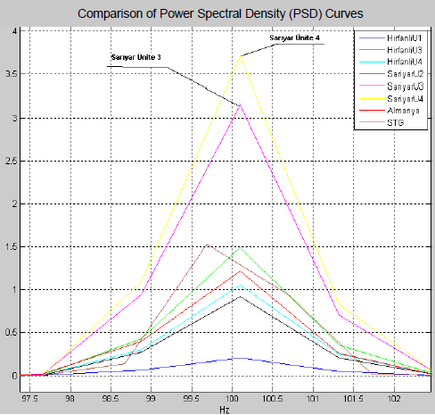
HYDRO · FLEET COMPARISON
Six generators at two hydro plants in Türkiye were assessed together. Five were in good condition. One showed loose foundation patterns, and two showed stator-related patterns below alarm level, marked for trending.
Case data from Artesis installations. Findings are shown by category, as e-PCM reports them. The hydro example is a fleet assessment, not a confirmed finding on the machine.
BEFORE YOU INSTALL
What an installation needs, and where generator monitoring from the terminals stops.
WHAT YOU NEED ON SITE
WHAT IT DOES NOT DO
e-PCM AND e-MCM
Each product has its own analysis, built for its machine. Monitor your generators with e-PCM and your motor-driven equipment with e-MCM, and see both in OmniSight.
e-PCM · GENERATOR MONITORING
Tell us the machine family, rating and duty. We will look at what e-PCM can see on it and what an installation needs.
Where continuous operation is crucial for maximum productivity, any failure in the smelting process can lead to substantial production delays and significant material costs. Artesis emerges as the ideal ally for the iron and steel industry, offering unparalleled condition monitoring tailored for challenging environments.
Artesis is here to support the energy sector with our advanced system for monitoring and predicting issues. In an industry where a steady power supply is crucial, our technology plays a key role in ensuring things run smoothly. Our special software is great at spotting potential problems early in rotating equipment, acting like an important early warning system. This is especially important in the energy sector, where unexpected breakdowns can lead to disruptive power outages affecting businesses, homes, and critical infrastructure. Artesis significantly contributes to the reliability of the energy sector by offering an effective predictive maintenance solution. By looking at patterns over time, our technology gives an early sign of possible issues. This helps grid operators plan ahead, taking actions to prevent power disruptions and ensuring a constant energy supply to industries and communities.
The logistic and transportation industry faces significant challenges when it comes to downtime costs, with unplanned disruptions leading to schedule delays, missed delivery dates, and additional charges. Artesis plays a crucial role in minimizing these challenges by providing continuous monitoring of asset health, offering timely insights into the need for repairs.
Artesis introduces an advanced Predictive Maintenance (PdM) solution tailored for the automotive industry. Our system, Artesis e-MCM, is designed for simplicity, requiring minimal installation efforts and offering low start-up costs. With no need for sensor installation on equipment and the ability to function in non-EX areas, Artesis e-MCM is an ideal solution for inaccessible automotive equipment.
The food and beverage industry faces unique challenges, particularly concerning hygienic standards and safety. Artesis condition monitoring products emerge as a solution, offering a distinctive advantage—no sensor installation on the equipment itself. This not only ensures uncompromised hygiene but also addresses safety concerns seamlessly.
Artesis’s condition monitoring and predictive maintenance solutions offer a comprehensive approach, encompassing failure prediction, fault diagnosis, failure-type classification, and recommendations for relevant maintenance actions. This empowers pharmaceutical equipment manufacturers, engineers, and process plant owners and operators to proactively identify and address potential issues, enhancing the efficiency of their maintenance services and improving equipment uptime.
Artesis empowers water companies with continuous monitoring of aerators, centrifugal pumps, positive displacement pumps, mixers, clarifiers, and submerged equipment, preventing potential failures and optimizing asset performance and energy consumption. In the water industry, system downtime is both disruptive and costly. Artesis’s predictive maintenance and power monitoring solutions enhance operational efficiencies, prevent unplanned downtime, and extend the economic life of critical assets.
Knowing how rotating equipment is performing, predicting failures, improving asset utilization, and finding productivity enhancements in challenging environments are particular challenge for Oil & Gas companies. Artesis helps oil and gas companies predict their rotating equipment failures and prevents the unplanned downtime where the cost of downtime is extremely high. When oil and gas operations break down, it can have a significant domino effect on energy supply – making predictive maintenance technology a key ally for companies in the sector.






 White Papers
 Case Study
 Documents
 Webinars
 Events
 ROI Calculator
 FAQ