
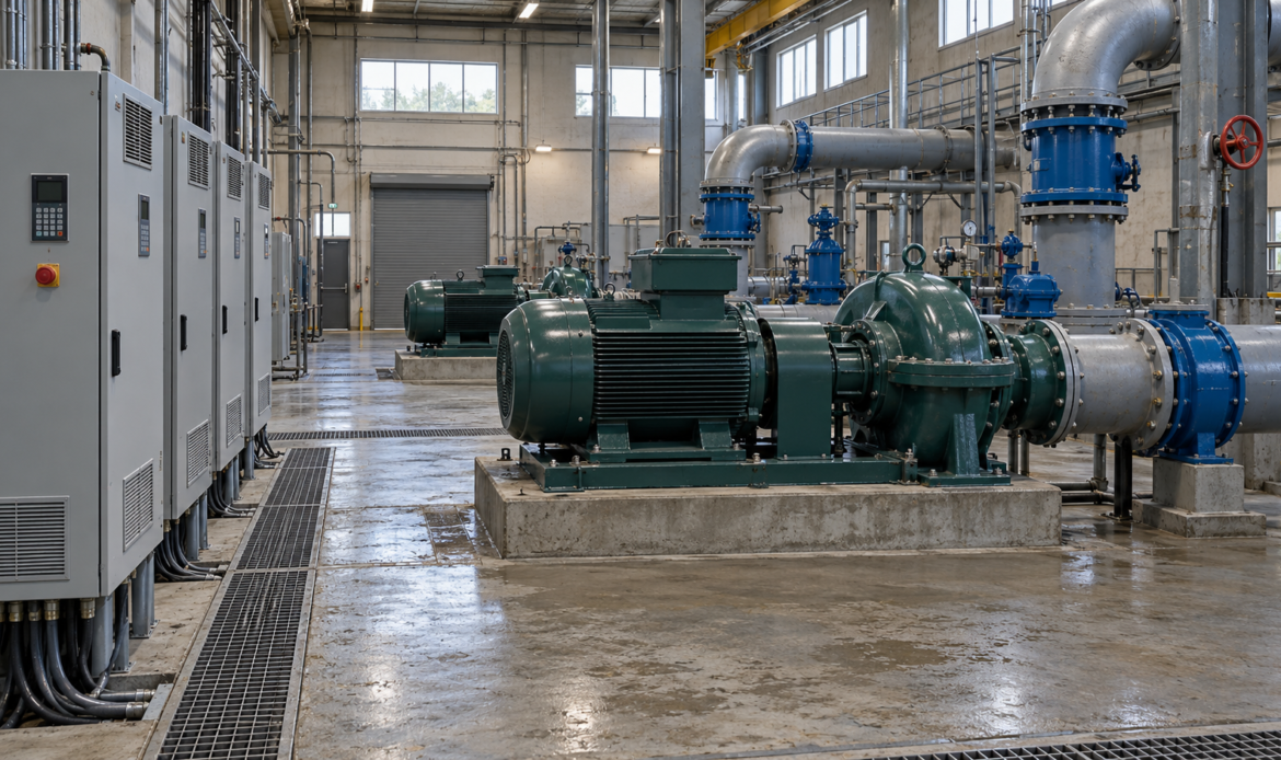
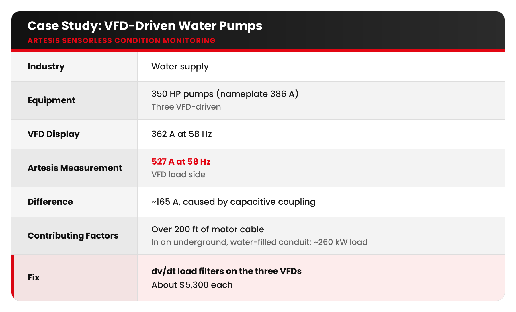
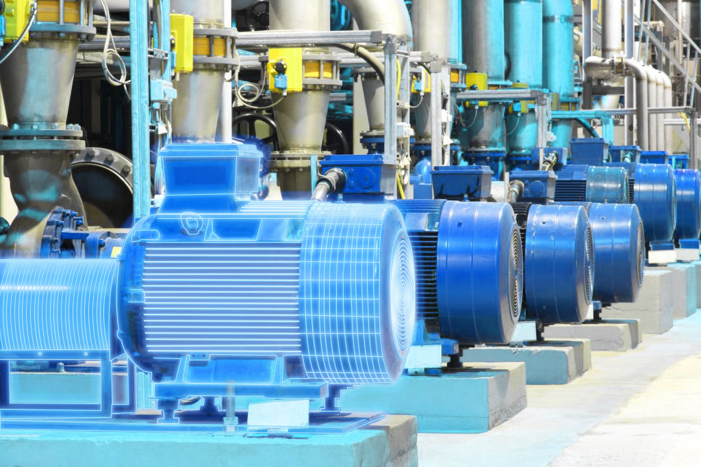
The pump station supplies water to a mid-sized US city. It has seven 350 HP pumps, three of them driven by VFDs. In late 2023, the engineering team started an annual Artesis motor circuit analysis programme on all seven pumps. Nobody expected the first report to question the numbers they looked at every day.
The discrepancy
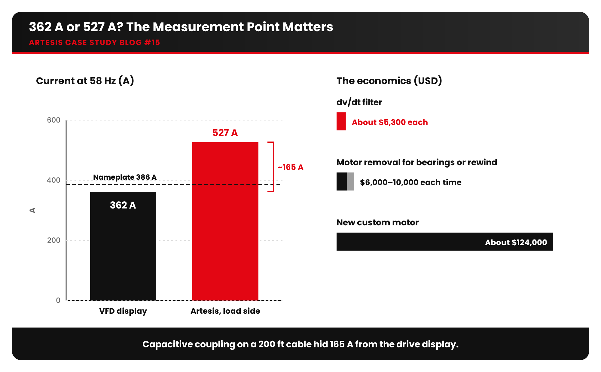
The VFD display read 362 amps at 58 Hz. At the same moment, Artesis, measuring on the load side of the VFD, read 527 amps at 58 Hz. The motor’s nameplate current is 386 A. According to the drive, the motor was comfortably under its rating. According to the measurement at the motor side, it was well over.
The explanation was capacitive coupling. More than 200 feet of motor cable ran through an underground conduit filled with water. With the fast-switching output of the VFD, that long cable run behaves like a capacitor, and a large extra current, about 165 A, was flowing that the drive’s own reading did not show.
That extra current stresses the motor through overheating, bearing damage from high-frequency currents and a shorter insulation life.
The fix and the payback
The team shared the data with a VFD specialist from the drive manufacturer, who came to site to see the Artesis measurements. The recommendation was to install dv/dt load filters on each of the three VFDs.
After installation, the motors ran within their design parameters, noticeably cooler, and both the VFD and motor were audibly quieter. The economics were clear:
- dv/dt filter materials: about $5,300 each
- Removing a motor for bearing replacement or rewinding: $6,000–$10,000 each time
- A new custom motor: about $124,000
“Artesis was able to capture something that we would never have caught,” the team wrote in their review.
Why voltage, current and frequency are the foundation
Every diagnostic conclusion rests on accurate basic measurements:
- Voltage: under- or over-voltage changes motor current, torque, heating and efficiency. A rule of thumb is that ±10% of rated voltage is the typical tolerance limit.
- Current: the direct indicator of motor loading and heating. Nameplate current is the reference.
- Frequency: sets the motor speed. On VFD drives, it must be read correctly for every frequency-based diagnosis.
Common problems with V / I / F
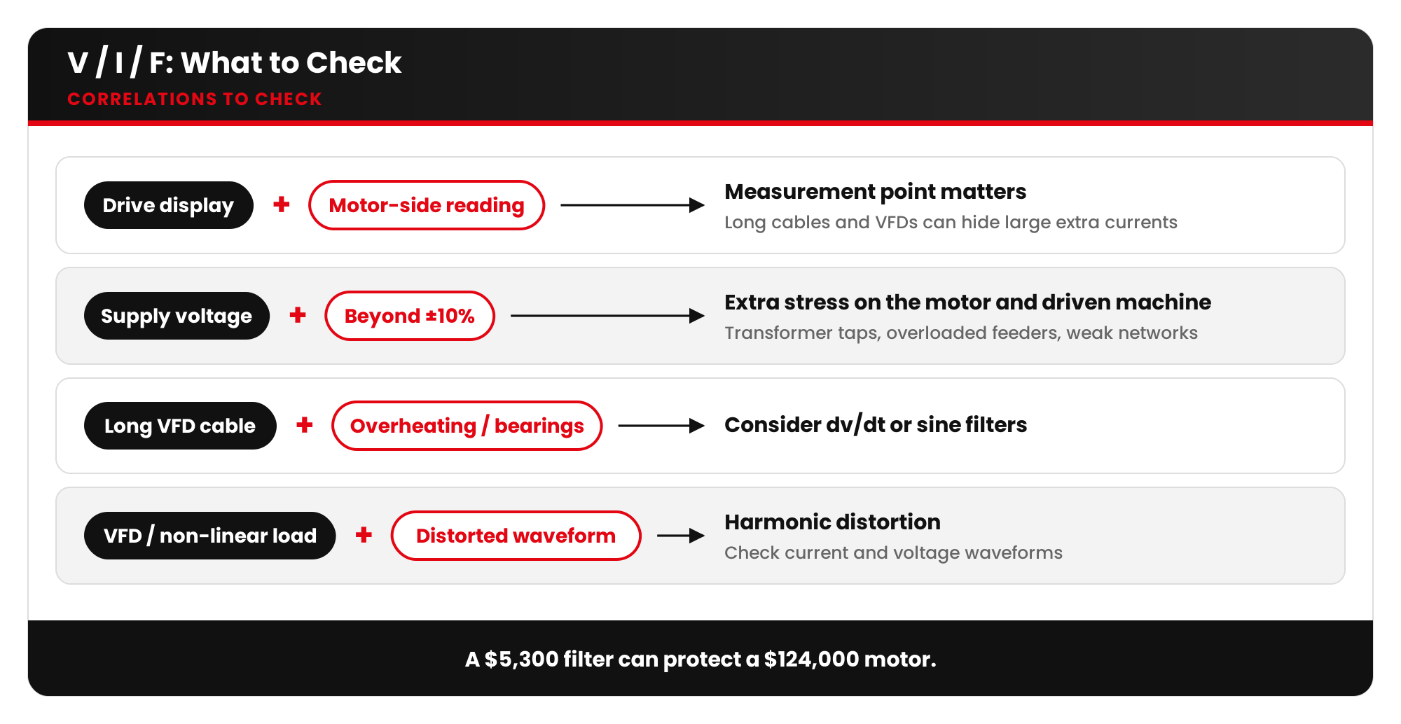
- Measurement point matters: drive displays, protection relays and motor-side measurements can disagree, especially with long cables and VFDs.
- Supply voltage deviations from transformer tap settings, overloaded feeders or weak networks.
- Voltage variation beyond ±10%, as seen in another Artesis case on a metal press, which adds stress to the motor and the driven machine.
- Harmonic distortion from VFDs and non-linear loads, which distorts current and voltage waveforms.
- Frequency instability on island or generator-fed networks.
What errors or deviations lead to
- Motors running overloaded while displays say they are fine
- Overheating, insulation ageing and bearing damage
- Nuisance trips, or protection that never trips when it should
- Wrong maintenance decisions based on wrong numbers
Checklist
- Know where every current reading is measured: drive, relay, MCC or motor terminals.
- On VFD drives with long cables, measure on the motor side and compare.
- Check supply voltage against ±10% of rated and trend it over time.
- Consider dv/dt or sine filters for long motor cable runs.
- Record V, I and F in every condition assessment as the baseline for diagnosis.
Key takeaways
- Basic electrical parameters are the foundation of every diagnosis, so measure them where they matter.
- Long VFD cable runs can hide large extra currents.
- A $5,300 filter can protect a $124,000 motor.
Are your drive displays telling the whole story? Ask Artesis about an AMT Pro motor circuit assessment.








 White Papers
 Case Study
 Documents
 Webinars
 Events
 ROI Calculator
 FAQ