Install at the cabinet.
Three-phase voltage and current. Voltage direct up to 690 V line to line, through PTs above that; current through CTs. DOL, star-delta, soft-starter and VFD-fed motors. No motor size ceiling.

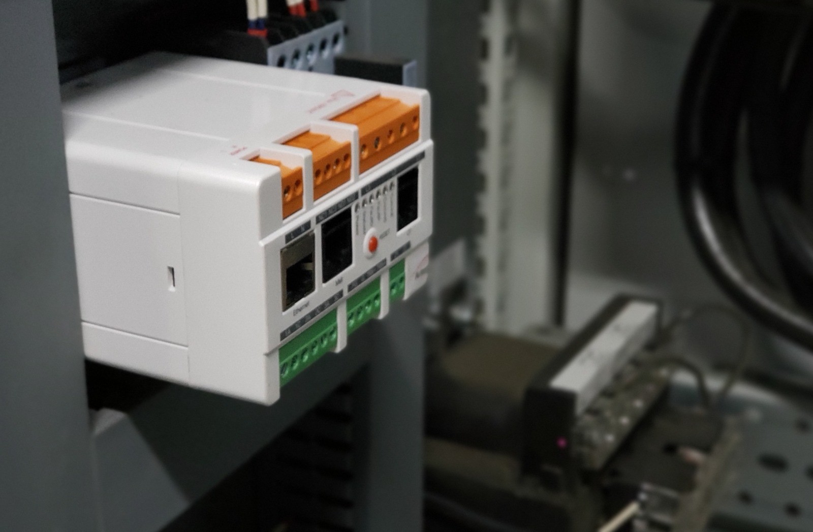
WATCH e-MCM

Artesis e-MCM: continuous monitoring from the motor control cabinet.
HOW IT WORKS
Current and voltage carry information about the motor and the load it drives. e-MCM measures them continuously at the cabinet and compares each reading with the model it learned for that machine.
Three-phase voltage and current. Voltage direct up to 690 V line to line, through PTs above that; current through CTs. DOL, star-delta, soft-starter and VFD-fed motors. No motor size ceiling.
e-MCM builds a model of each machine from its own electrical behaviour, across the load and speed points it runs at. After an overhaul it relearns, so the repaired condition becomes the new reference.
Each reading is compared with the model. Persistent deviations are flagged by fault category in Normal, Caution and High; operating-point clustering and persistence reduce false alarms. Findings go to OmniSight, where Artesis Insight AI writes them up.
STATOR HEALTH
e-MCM learns each motor's electrical model and checks the stator against it continuously, at each operating point it has learned. Four checks run together.
The motor's internal electrical parameters are recalculated continuously and compared with the learned model. A persistent rise flags a developing motor-side condition.
Negative-sequence current is trended in amplitude and phase angle, which identifies the phase involved.
Stator-related patterns in the current spectrum are tracked against the learned baseline.
Current imbalance is judged against voltage imbalance, so a supply problem is not reported as a winding fault.
WINDING OR CONNECTION
The stator engine separates a turn-to-turn winding pattern from a high-resistance connection pattern and identifies the affected phase. It reports the pattern, not a severity.
INSULATION
On motors, progressive insulation-related trends are tracked too. Confirm with a Megger, surge comparison or PD test.
OFFLINE ONLY
Early-stage insulation changes, open circuits, phase-to-ground faults and shorted laminations need a de-energized test. Online monitoring does not cover them.
IN THE FIELD
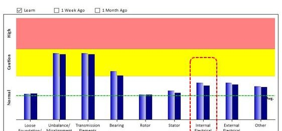
A 6.6 kV, 355 kW vertical pump motor was monitored with e-MCM. Its Internal Electrical parameter moved into Caution. The site inspected and overhauled the motor, and used e-MCM to check whether each fix had worked.
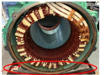
e-MCM → FOUND ON SITE
e-MCM flagged a developing motor-side condition. An offline test followed.
Water condensation in the main terminal box, rust marks at the spigots and end shields, low insulation resistance.
Stator washed, baked and varnished. e-MCM still showed the Internal Electrical fault.
Two space heaters fitted at the winding overhang. e-MCM then relearned the motor.
Internal Electrical is now within the normal range. Monitoring continues.
MORE FROM THE FIELD
ELECTRICAL · SUPPLY
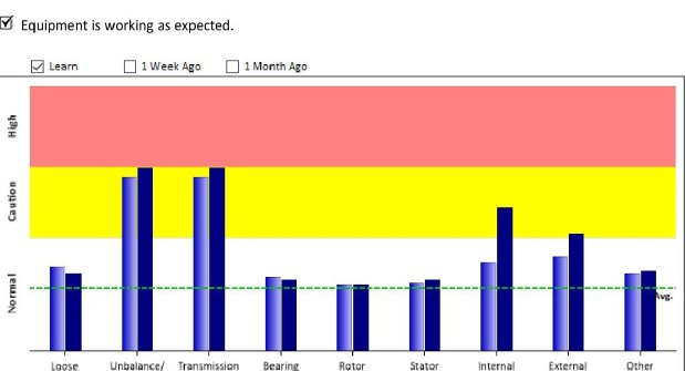
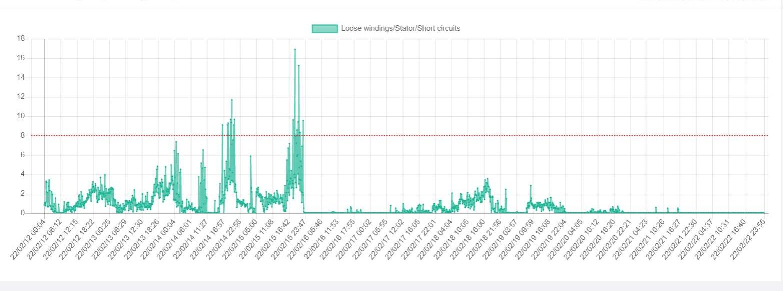
On a positive displacement blower at a US water facility, e-MCM flagged the external electrical category, and the bearing trend rose with it. An infrared scan found hot spots at the weather head and corroded connections at the motor and the MCC. After re-termination both trends dropped and stayed down.

"We would have never found the fault without the Artesis MCSA system."Monty Sedlak, Project Director, Jacobs
MECHANICAL
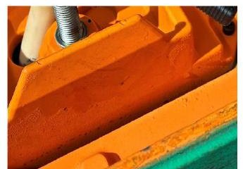
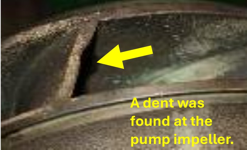
On a 3.3 kV deep-well submersible raw water pump, e-MCM flagged unbalance and looseness. The plant's separate vibration sensor on the pump casing read high on the suction side. When the pump was pulled, wooden debris had dented the impeller.
Photos and reports from customer sites, shared by Artesis partners and customers. Findings are shown the way e-MCM reports them: by category, then confirmed on the machine.
CONTINUOUS MONITORING
A portable test shows the motor on the day it is tested. e-MCM follows it between tests.
CONFIRM THE FIX
After maintenance, the fault category should fall back. If it does not, as with the pump motor above, the trend shows it.
RELEARN
After an overhaul or a process change, e-MCM relearns the motor, so the repaired condition becomes the baseline.
COME AND GO
Supply events, load changes and faults that appear only at certain operating points are recorded when they happen.
ALARMS
Relay outputs for local alarms, and data to SCADA, DCS and existing monitoring platforms.
THE e-MCM UNIT
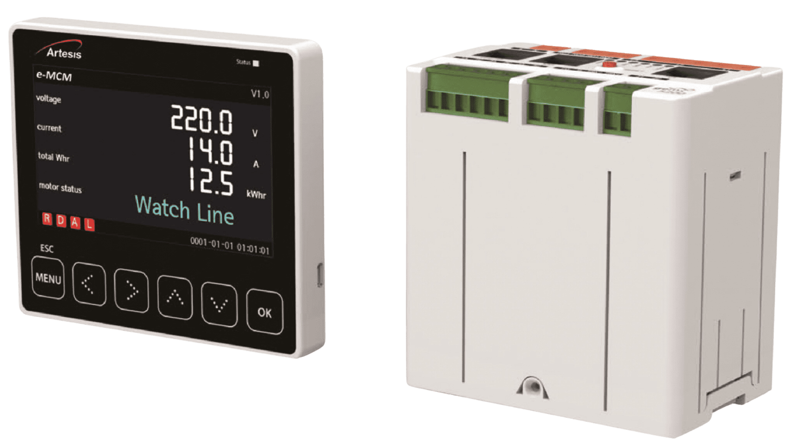
e-MCM mounts in the motor control cabinet and measures three-phase voltage and current. Results show on the unit, go to your plant systems, and feed OmniSight in the cloud or on premises.
Voltage direct up to 690 V line to line, through PTs above that. Current through CTs, up to 2,500 A.
DOL, star-delta, soft-starter and VFD-fed motors, 15 to 120 Hz. No motor size ceiling.
Display with measurements and fault status, status LEDs, and relay outputs for alarms.
Modbus TCP over Ethernet, and Modbus RTU over RS-485 for metering values. Connects to SCADA, DCS and existing monitoring platforms.
Voltage, current, power, power factor, imbalance, harmonics and energy use on each monitored motor.
Fleet view, Artesis Insight reports, cost analysis and pump performance. Explore OmniSight.
BEFORE YOU INSTALL
What an installation needs on site, and where continuous monitoring stops.
WHAT YOU NEED ON SITE
WHAT IT DOES NOT DO
e-MCM AND AMTPro
The two work together but do not do the same job. e-MCM learns each motor's model and watches it continuously, which gives the deeper stator assessment and, with OmniSight, pump performance. AMTPro tests the rest of the plant on a route, with its own report and Artesis Insight write-up. Used together, they cover your motor fleet, with the level of monitoring matched to each asset's criticality.
e-MCM · CONTINUOUS MONITORING
Tell us what you run. We will look at where continuous monitoring fits and what an installation needs.
Where continuous operation is crucial for maximum productivity, any failure in the smelting process can lead to substantial production delays and significant material costs. Artesis emerges as the ideal ally for the iron and steel industry, offering unparalleled condition monitoring tailored for challenging environments.
Artesis is here to support the energy sector with our advanced system for monitoring and predicting issues. In an industry where a steady power supply is crucial, our technology plays a key role in ensuring things run smoothly. Our special software is great at spotting potential problems early in rotating equipment, acting like an important early warning system. This is especially important in the energy sector, where unexpected breakdowns can lead to disruptive power outages affecting businesses, homes, and critical infrastructure. Artesis significantly contributes to the reliability of the energy sector by offering an effective predictive maintenance solution. By looking at patterns over time, our technology gives an early sign of possible issues. This helps grid operators plan ahead, taking actions to prevent power disruptions and ensuring a constant energy supply to industries and communities.
The logistic and transportation industry faces significant challenges when it comes to downtime costs, with unplanned disruptions leading to schedule delays, missed delivery dates, and additional charges. Artesis plays a crucial role in minimizing these challenges by providing continuous monitoring of asset health, offering timely insights into the need for repairs.
Artesis introduces an advanced Predictive Maintenance (PdM) solution tailored for the automotive industry. Our system, Artesis e-MCM, is designed for simplicity, requiring minimal installation efforts and offering low start-up costs. With no need for sensor installation on equipment and the ability to function in non-EX areas, Artesis e-MCM is an ideal solution for inaccessible automotive equipment.
The food and beverage industry faces unique challenges, particularly concerning hygienic standards and safety. Artesis condition monitoring products emerge as a solution, offering a distinctive advantage—no sensor installation on the equipment itself. This not only ensures uncompromised hygiene but also addresses safety concerns seamlessly.
Artesis’s condition monitoring and predictive maintenance solutions offer a comprehensive approach, encompassing failure prediction, fault diagnosis, failure-type classification, and recommendations for relevant maintenance actions. This empowers pharmaceutical equipment manufacturers, engineers, and process plant owners and operators to proactively identify and address potential issues, enhancing the efficiency of their maintenance services and improving equipment uptime.
Artesis empowers water companies with continuous monitoring of aerators, centrifugal pumps, positive displacement pumps, mixers, clarifiers, and submerged equipment, preventing potential failures and optimizing asset performance and energy consumption. In the water industry, system downtime is both disruptive and costly. Artesis’s predictive maintenance and power monitoring solutions enhance operational efficiencies, prevent unplanned downtime, and extend the economic life of critical assets.
Knowing how rotating equipment is performing, predicting failures, improving asset utilization, and finding productivity enhancements in challenging environments are particular challenge for Oil & Gas companies. Artesis helps oil and gas companies predict their rotating equipment failures and prevents the unplanned downtime where the cost of downtime is extremely high. When oil and gas operations break down, it can have a significant domino effect on energy supply – making predictive maintenance technology a key ally for companies in the sector.







 White Papers
 Case Study
 Documents
 Webinars
 Events
 ROI Calculator
 FAQ
FAQ